The Wonderful World of Dissocia 2023: Difference between revisions
No edit summary |
|||
| (23 intermediate revisions by one other user not shown) | |||
| Line 3: | Line 3: | ||
[[Category:New Athenaeum]] | [[Category:New Athenaeum]] | ||
{| style=" border: 4px solid # | {| style=" border: 4px solid #095392; background-color: #5CB5FF; float: right; clear: right; margin: 2px; width: 22em;" | ||
! style="background-color: # | ! style="background-color: #095392; font-size: 150%;" align="center" colspan="2"| <span style="color: #FFFFFF;">'''{{PAGENAME}}'''</span> | ||
|- | |- | ||
|align="center" | [[File:Dissocia_Balloons.jpg|200px]] | |align="center" | [[File:Dissocia_Balloons.jpg|200px]] | ||
|- | |- | ||
! style="background-color:# | ! style="background-color:#095392; font-size: 120%;" align="center" colspan="2"| <span style="font-family: Tahoma "> <span style="color: #FFFFFF;">'''Summary'''</span> | ||
|- | |- | ||
|'''Dates''' <div style="text-align: centre;"> 08-11-2023 - 10-11-2023 </div> | |'''Dates''' <div style="text-align: centre;"> 08-11-2023 - 10-11-2023 </div> | ||
| Line 16: | Line 16: | ||
|'''Location''' <div style="text-align: centre;"> New Athenaeum </div> | |'''Location''' <div style="text-align: centre;"> New Athenaeum </div> | ||
|- | |- | ||
! style="background-color:# | ! style="background-color:#095392; font-size: 120%;" align="center" colspan="2"| <span style="font-family: Tahoma"> <span style="color: #FFFFFF;">'''Creative Team'''</span> | ||
|- | |- | ||
|'''Director''' <div style="text-align: centre;"> Finn Den Hertog </div> | |'''Director''' <div style="text-align: centre;"> Finn Den Hertog </div> | ||
| Line 28: | Line 28: | ||
|'''Lighting Designer''' <div style="text-align: centre;"> Kai Fischer </div> | |'''Lighting Designer''' <div style="text-align: centre;"> Kai Fischer </div> | ||
|- | |- | ||
! style="background-color:# | ! style="background-color:#095392; font-size: 120%;" align="center" colspan="2"| <span style="font-family: Tahoma"> <span style="color: #FFFFFF;">'''Production Team'''</span> | ||
|- | |- | ||
|'''Head of Stage''' <div style="text-align: centre;"> [[Noah Dunnett]] </div> | |'''Head of Stage''' <div style="text-align: centre;"> [[Noah Dunnett]] </div> | ||
| Line 73: | Line 73: | ||
==Lighting== | ==Lighting== | ||
Lighting for the Wonderful World of Dissocia had several unique challenges on this version of the production. The first to look at is the flying pendant light fixture which had to be installed on the auditorium side of the proscenium arch. To achieve this, a system of pulleys and wire rope fairleads was used to allow both the control line for the pendant, and the power cable to move | Lighting for the Wonderful World of Dissocia had several unique challenges on this version of the production. The first to look at is the flying pendant light fixture which had to be installed on the auditorium side of the proscenium arch. To achieve this, a system of pulleys and wire rope fairleads was used to allow both the control line for the pendant, and the, power cable to move therefore lowering in/raise out the pendant light fixture. | ||
The | The basic idea would be to utilise a domestic hanging pendant light and have this rise and fall: | ||
<BR> | <BR> | ||
[[File:Basic Idea.jpg|600px]] | [[File:Basic Idea.jpg|600px]] | ||
| Line 90: | Line 90: | ||
The rigging would be relatively conventional and just need to have a support arm in scaff from the catwalks, as well as an upright scaff to support a tension line: | The physical rigging would be relatively conventional and just need to have a support arm in scaff from the catwalks, as well as an upright scaff to support a tension line: | ||
<BR> | <BR> | ||
| Line 98: | Line 98: | ||
<BR> | <BR> | ||
To ensure that the cable powering the pendant could be flown in and out smoothly, along with the physical pendant, the cable was was supported by swing cheek pulleys which ran along a tensioned steel wire rope: | To ensure that the cable powering the pendant could be flown in and out smoothly, along with the physical pendant, the cable was was supported by swing cheek pulleys which ran along a tensioned steel wire rope. The pulleys to divert the lifting rope (string) were in fact wire rope fairleads. These are sets of 4 rollers, held in a metal frame which allow a rope or steel wire to be pulled around an angle whilst always receiving a frictionless draw due to always being pulled across a roller: | ||
<BR> | <BR> | ||
[[File:Top View - Pulleys.jpg]] | [[File:Top View - Pulleys.jpg]] | ||
| Line 110: | Line 110: | ||
Image:Flying Pendant 2.jpg|Pulleys | Image:Flying Pendant 2.jpg|Pulleys | ||
Image:Flying Pendant 3.jpg|Upright Pole - Note the wire rope fairlead diverting the control line | Image:Flying Pendant 3.jpg|Upright Pole - Note the wire rope fairlead diverting the control line | ||
Image:Flying Pendant 4.jpg|Top view - Note wire rope fairlead | Image:Flying Pendant 4.jpg|Top view - Note the wire rope fairlead | ||
</gallery> | </gallery> | ||
<BR> | |||
The final lamp looked really good and operated well: | |||
<BR> | |||
[[File:Dissocia_-_Lamp_and_Pendant.JPG|600px]] | |||
<BR> | <BR> | ||
<BR> | <BR> | ||
Another prop/set item the LX dept | Another prop/set item the LX dept worked on was the wireless battery powered hurricane Lamp. This lamp was simply adapted to have am SES/E14 bulb holder mounted inside. Via an installed switch, a 9v battery was wired to the lamp holder. A nicely shaped T25 lamp with LED filaments was used to give a good amount of light. The bulb used runs at 12v, and was bought from Amazon via a supplier called Bonlux. | ||
The end result looked like this: | The end result looked like this: | ||
<BR> | <BR> | ||
[[File:Hurricane Lantern 6.jpg|600px]] | [[File:Hurricane Lantern 6.jpg|600px]] | ||
<BR> | <BR> | ||
In making the lantern, it require a little modification to widen a hole for the lamp holder to fit. This was done by widening the wick holder. The lamp holder was mounted on some M10 threaded rod which is hollow (a common part in Chandelier making). With washers and locking nuts, the lamp holder was mounted to sit in place in the centre of the lantern. Two wires were simply soldered onto the switch for operation and a "battery clasp" for a 9v battery was added to give power - polarity is simply Red to Brown and onto the switch, and black to blue wire straight to the lamp holder. As the bulb was actually very bright, a piece of Lee 1.2 Stop Neutral Density was wrapped around the bulb to dim it slightly. The power supply used on this show was a 9v Lithium Ion battery which was USB-C rechargeable. | |||
<gallery> | <gallery> | ||
Image:Hurricane Lantern 1.jpg|Complete lantern - Bunjee cord with hook for securing Base and red/brow blue/black wiring polarity | Image:Hurricane Lantern 1.jpg|400px|Complete lantern - Bunjee cord with hook for securing Base and red/brow blue/black wiring polarity | ||
Image:Hurricane Lantern 2.jpg|SES\E14 lamp holder and Switch | Image:Hurricane Lantern 2.jpg|400px|SES\E14 lamp holder and Switch | ||
Image:Hurricane Lantern 3.jpg|Lamp holder with M10 hollow threaded rod | Image:Hurricane Lantern 3.jpg|400px|Lamp holder with M10 hollow threaded rod | ||
Image:Hurricane Lantern 4.jpg|Lamp holder from inside base and switch | Image:Hurricane Lantern 4.jpg|400px|Lamp holder from inside base and switch | ||
Image:Hurricane Lantern 7.jpg|9v Lithium Ion USB-C rechargeable battery | Image:Hurricane Lantern 7.jpg|400px|9v Lithium Ion USB-C rechargeable battery | ||
Image:Bonlux 12v T25.jpg|LX Dept have spare stock of same bulb | |||
</gallery> | </gallery> | ||
<BR> | |||
The lighting design for show show was delivered by Kai Fischer and drawn in AutoCAD. As AutoCAD operates differently to Vectorworks and doesn't contain symbol data within the DWG export, the PLX had to import the DWG file into Vectorworks, and redraw the lighting symbols into the VWX file to allow for file referencing with other depts. By utilising the Vectorworks "Data Visualisation Tool", the LD's plan could be highlighted in RED, and then the VWX symbols laid on top in standard BLACK. This meant that wherever the LD had a symbol drawn, the PLX could be sure of having put the correct VWX symbol in the same place. Any RED symbol, without a VWX symbol on top, meant a fixture had been missed in transcribing the plan! This also worked whenever the LD updated his plan and moved/changed fixtures, as the new plan could be coloured differently again (say green) and overlaid showing changes. | |||
<BR> | |||
[[File:Edit_Visualisation_Data.jpg|700px]] | |||
<BR> | <BR> | ||
[[Media:LX Plans - Dissocia - Overhead Rig.pdf|Booklet of Overhead Plans (Dimmers, Socapex, DMX, 16A etc)]] | |||
<BR> | |||
[[Media:LX PLans - Dissocia FoH.pdf|Front of House Plan]] | |||
<BR> | |||
[[Media:LX PLans - Dissocia Pros and Slips.pdf|Booklet of Pros and Slips Plans (Dimmers, Socapex, DMX, 16A etc)]] | |||
<BR> | |||
[[Media:LX Plans - Dissocia - On Stage Booms.pdf|Booklet of On Stage Booms Plans (Dimmers, Socapex, DMX, 16A etc)]] | |||
<BR> | |||
[[Media:LX Plans - Dissocia - Roof and Birdies.pdf|Roof and Birdie Bar plans]] | |||
<BR> | |||
[[Media:Dissocia_PLX_-_preparatory_planning_-_plans_1st_draft.pdf|PLX's 1st Draft of cable plans showing dimmer assignment and cable call]] | |||
<BR> | |||
[[Media:Dissocia PLX - preparatory planning - colour call first draft.pdf|PLX's 1st Draft of colour call - data from original DWG not available to export into LightWrite so completed manually]] | |||
<BR> | |||
As the plans in the above documents show, the on stage LX rig was relatively extensive, whilst the overhead rig was quite light. This meant there were a lot of booms on stage. To facilitate the major set change between Acts 1 & 2, 4 booms were on wheels, allowing them to move out of the way during the set change. To make the entire LX rig easier, multiple looms of socapex, 16amp, DMX and 15amp cables were made. This meant every LX bar could acutally be flown right in to stage level if the excess trip was lowered over the fly floor. Also, in relation to the booms, for the major Act2 scene change their Socapex, 16A and DMX could easily be unplugged, and then the 4 booms ( 2 x SL and 2 x SR) were moved to sit against the rear wall of the Athenaeum, either side of the sets "falling wall". This also allowed for the dog leg masking to be hoisted up and out of the way, giving more stage access to the wheeled trucks on to which "Psychiatric Ward" set was mounted. | |||
The ceiling piece of the Act 2 set, prevent any normal top light from being able to light the performers. To counter this, the LD devised a drop bar of 22 x birdies (Par16) with 75w tungsten halogen lamps. These were a mix of 20 x 36degree and 2 x 24 degree lamps. All the units had their 12v power supply rigged on the fly bar just above the drop bar, and were run from Athenaeum ChilliePro dimmers. As many of the units were paired, giving a load of 150w per dimmer, their dim curve was surprisingly good! | |||
<BR> | |||
[[File:Birdie Bar - Dissocia.jpg|Birdie Drop Bar During Rigging|350px]] [[File:Birdie Bar - Dissocia 2.jpg|Birdie in use during a scene (hidden by top masking)|700px]] | |||
<BR> | |||
To add to the effect of the Act 2 set appearing to look like a working Psychiatric Ward, two ceiling lights were installed in the roof piece of the set. They had the look of recessed fluorescent tube light fittings, and the LD wished to keep the same effect of light out put that would be achieved by a fitting of this type, but also asked for the ability to give colour. Some special, high brightness 24v non spotting RGBW (4000kelvin "natural white") tape was bought to be installed in the fitting: | |||
<BR> | |||
[[File:Dissocia - Ceiling Light 4.jpg|350px]] [[File:Dissocia - Ceiling Light 3.jpg|350px]] | |||
<BR> | |||
The LED tape was simply affixed to the interior of the light fitting with strong clear tape. The tape was then covered with a frosted acrylic half tube to give the visual effect of a fluorescent tube. The original lighting control gear for fluorescent tubes was left in place to avoid any accidental damage to the fitting by removing it. | |||
<BR> | |||
<BR> | |||
[[File:Dissocia - Ceiling Light.jpg|700px]] | |||
<BR> | |||
The lights were mounted by dropping the egg crate section into pre cut holes in the ceiling piece, and working with TSD, wooden battens were affixed to the edges to support the lights, and stop them dropping through the holes. Two 4 channel LED drivers and a single 100w PSU was mounted to the rear of the ceiling piece. These were linked between the SR and SL sides with a 3pin DMX cable and some 2 core cable. Using two drivers allowed the LED some finer control over the two light fixtures and on occasion to run some simple effects to give flickers at random, rather than having both lights linked to one driver. During the set change over, a 16a and DMX cable was attached to a hanging plate via a sling, and then plugged into the power and data inputs for the driver. A simple RGBW chase was run through the ceiling lights as part of the "Working Light" LX cue, to ensure that both ceiling lights were working during the set changeover. | |||
Finally, when installed, the lights looked very convincing, provided a high brightness when viewed (although didnt cast much light themselves) and worked to keep the colour pallet of the design matched when using some LED fixtures to give colour to the set. | |||
<BR> | |||
<BR> | |||
[[File:Bike Light - Dossocia 1.jpg|450px]] [[File:Bike Light - Dossocia 2.jpg|500px]] [[File:Bike Light - Dossocia 3.jpg|500px]] | |||
<BR> | |||
The tricycle set item also required a simple light to be fitted. This was 12v "fog lamp" type unit that makes use of a 12v H1 type bulb from the automotive industry. A 12v sealed lead acid battery was mounted on the front of the tricycle and hidden by the basket on the front. A 2 way switch was mounted onto the handle bars that allowed the rider to flick one way and flash, or flick the other way for constant on. This type of switch was called a "SPDT, On-Off-(On)". This means: | |||
SP - Single Pole - SP switches control only one electrical circuit | |||
DT - Dual Throw - DT switches close a circuit in the Up position, as well as the Down position (On-On) or other variations | |||
"On-Off-(On)" - This describes the three operating positions of the switch and their function. "ON", with no brackets means a latched on state, meaning the switch is open, and held open by the mechanics in the switch itself. "OFF" with no brackets, means a latched Off, and the switch is held in this position by mechanics within the switch. "(On)" within brackets, indicates that this state is momentary or not maintained. The switch is only in this position for the moment it is held or pushed there by the user, and only the user can keep the switch in this state. Otherwise, it will return to the middle state, which is latched off. | |||
You can see the example of this type of switch in the first picture above, and how the switch would then operate to switch on/off or flash the light. | |||
<BR> | |||
The show made use of some Wireless DMX to allow a domestic standing lamp to be very easily moved around the stage during the performance. Having the lamp wirelessly controlled, allowed the LD to add it into lighting cues and effects (such as flickering during scenes to match the rest of the rig). The lamp was a borrow from the RCS prop stores, and with a slight modification to the bayonet lamp fitting, a 12v dimmable LED bulb was fitted. The standing lamp, being vintage had a 1/2inch threaded lamp holder, rather than an M10 lamp holder, so a lamp holder had to be specially sourced and ordered from an online lamp and chandelier website. The lamp holder was controlled/powered via a hired wireless RGB LED driver. The power supply was a 20,000mAh USB battery bank that used a step up voltage adapter. The USB 5v to 12v step up transformer gave us a max power of 1Amp @ 12v - this was more than enough as the bulb was only 4w at 12v (0.3amps!). This meant the lamp could be on and last for well over the duration of he show. The wireless DMX system was a Wireless Solution G4 Transceiver (set in transmit) and a custom RGB dimmer/driver card with a Wireless Solutions DMX receiver built into a black plastic enclosure. The system worked really well. | |||
<BR> | |||
[[File:Standing Lamp - Dissocia.jpg|700px|Wireless Lamp in situ]] | |||
<gallery> | |||
Image:Lamp Holder - half inch thread 1.jpg |400px| 1/2inch thread lamp holder | |||
Image:Lamp Holder - half inch thread 2.jpg |400px| drilled out lamp holder | |||
Image:Wireless DMX Kit 1.jpg|400px| DMX Kit used and mounted inside the top of the standing lamp (USB battery bank, step up power supply and wireless RGB dimmer) | |||
Image:Wireless DMX Kit 2.jpg|400px| Transmitter setup in Ath control room | |||
</gallery> | |||
<BR> | |||
With several practicals and quite a substantial Act1 to Act2 set change, the power up and pre show checks were key to ensuring a good rig and running of the show: | |||
[[Media:PLX_-_Dissocia_Power_Up-Down_Procedure_and_Pre_Shows.pdf|PLX powerup/down and pre show checks]] | |||
<BR> | |||
==Sound== | ==Sound== | ||
==Stage Management== | ==Stage Management== | ||
Latest revision as of 18:58, 2 March 2024
| The Wonderful World of Dissocia 2023 | |
|---|---|

| |
| Summary | |
| Dates 08-11-2023 - 10-11-2023
| |
| Performance Course Third Year BA Acting
| |
| Location New Athenaeum
| |
| Creative Team | |
| Director Finn Den Hertog
| |
| Set Designer | |
| Costume Designer | |
| Sound Designer | |
| Lighting Designer Kai Fischer
| |
| Production Team | |
| Head of Stage | |
| Deputy Head of Stage | |
| Head of Flys | |
| Stage Manager Rebecca Munro
| |
| Deputy Stage Manager | |
| Assistant Stage Manager | |
| Assistant Stage Manager Vanessa Yi Heng Lam
| |
| LX Programmer | |
| PLX | |
| Lighting Technician | |
| Sound No.1 | |
| Production Sound Engineer | |
Overview
Technical Stage Department
"The Wonderful World of Dissocia" contained several challenges for TSD. The act 1 set consisted of a patchwork of carpets,a walkup trap and a 6000x4860mm flat that needed to fall at the end of the act. The act 2 set consisted of 3 steel deck trucks and a roof piece which came together to create the psych ward, this was then completely boxed in with black masking.
Falling Wall
At the end of act 1 the designer requested that the large sky flat at the back would fall leaving behind only a door that an actor would then step through.To do this we used a rather simple approach relying mostly on pin hinges. The falling wall was made of 3 separate flats meaning care had to be taken to avoid the flat flexing and being damaged as it fell.To do this we installed two strengthening battons on the back of the falling wall, one near the top and one near the top of the door section.We then attatched 4 french braces to the back of the flat, these where what held up the flat during the show until it was time for them to fall.These braces came from the RCS stock and are usually used for hard masking. The wall was then walked up by a team of 7 and moved into position. 4 opera pin hinges where then screwed into the bottom edge of the front face of the flat and then into the floor, these where to keep the wall from moving forward as it fell.Another 4 opera pin hinges where then screwed into the french braces and the floor, these held the wall upright until it was time for the fall.
To operate the fall two crew members would enter from a gap in the void to behind the wall, on stage managements cue they would remove the pins on the hinges connecting the french braces to the floor, they would then stand on the braces until they were given the "Go". On the "Go" they would step off the braces,give a coordinated push on the back side of the flat to start the fall and run back into the void to avoid being seen by the audience. With this method once the wall starts falling there is no way of stopping it. For this reason there was a safety zone planned with an extra 1m buffer to keep the performer who was standing at the front of the stage safe.The stage manager would not give clearance for the pins to be pulled prior to the performer moving into this zone.
To reset the wall,7 crew members were required.4 were needed to walk the wall back up,with 2 pulling on the braces for assistance and at the ready to put the pins back in. The additional member was the stage supervisor who would call the lift and give assistance on the braces.
Lighting
Lighting for the Wonderful World of Dissocia had several unique challenges on this version of the production. The first to look at is the flying pendant light fixture which had to be installed on the auditorium side of the proscenium arch. To achieve this, a system of pulleys and wire rope fairleads was used to allow both the control line for the pendant, and the, power cable to move therefore lowering in/raise out the pendant light fixture.
The basic idea would be to utilise a domestic hanging pendant light and have this rise and fall:

However it would need controlled via a rope from somewhere off stage:

With this in mind a system would need to be installed within the Athenaeum gods to accommodate the rigging, and ensure that the control line for raising and lowering could be run into the ONSTAGE side of the proscenium or to somewhere it could be operated without needing a person in the Gods. To do this, the control line was routed into the cupboard just off the entrance into the Fly Floor.

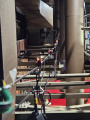
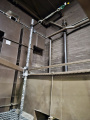
The physical rigging would be relatively conventional and just need to have a support arm in scaff from the catwalks, as well as an upright scaff to support a tension line:

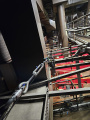
To ensure that the cable powering the pendant could be flown in and out smoothly, along with the physical pendant, the cable was was supported by swing cheek pulleys which ran along a tensioned steel wire rope. The pulleys to divert the lifting rope (string) were in fact wire rope fairleads. These are sets of 4 rollers, held in a metal frame which allow a rope or steel wire to be pulled around an angle whilst always receiving a frictionless draw due to always being pulled across a roller:

The final installation allowed the pendant to easily fly out as part of a cue, and then be lowered in for the Act 1 reset. The physical rigging looked like this:
-
 Tension Line
 -
 Pulleys
 -
 Upright Pole - Note the wire rope fairlead diverting the control line
 -
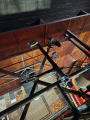 Top view - Note the wire rope fairlead


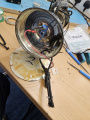
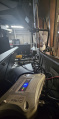
The final lamp looked really good and operated well:

Another prop/set item the LX dept worked on was the wireless battery powered hurricane Lamp. This lamp was simply adapted to have am SES/E14 bulb holder mounted inside. Via an installed switch, a 9v battery was wired to the lamp holder. A nicely shaped T25 lamp with LED filaments was used to give a good amount of light. The bulb used runs at 12v, and was bought from Amazon via a supplier called Bonlux.
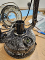
The end result looked like this:

In making the lantern, it require a little modification to widen a hole for the lamp holder to fit. This was done by widening the wick holder. The lamp holder was mounted on some M10 threaded rod which is hollow (a common part in Chandelier making). With washers and locking nuts, the lamp holder was mounted to sit in place in the centre of the lantern. Two wires were simply soldered onto the switch for operation and a "battery clasp" for a 9v battery was added to give power - polarity is simply Red to Brown and onto the switch, and black to blue wire straight to the lamp holder. As the bulb was actually very bright, a piece of Lee 1.2 Stop Neutral Density was wrapped around the bulb to dim it slightly. The power supply used on this show was a 9v Lithium Ion battery which was USB-C rechargeable.
-
 Complete lantern - Bunjee cord with hook for securing Base and red/brow blue/black wiring polarity
 -
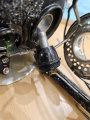
 SES\E14 lamp holder and Switch
 -
 Lamp holder with M10 hollow threaded rod
 -
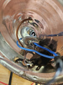 Lamp holder from inside base and switch
 -
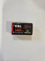 9v Lithium Ion USB-C rechargeable battery
 -
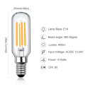 LX Dept have spare stock of same bulb


The lighting design for show show was delivered by Kai Fischer and drawn in AutoCAD. As AutoCAD operates differently to Vectorworks and doesn't contain symbol data within the DWG export, the PLX had to import the DWG file into Vectorworks, and redraw the lighting symbols into the VWX file to allow for file referencing with other depts. By utilising the Vectorworks "Data Visualisation Tool", the LD's plan could be highlighted in RED, and then the VWX symbols laid on top in standard BLACK. This meant that wherever the LD had a symbol drawn, the PLX could be sure of having put the correct VWX symbol in the same place. Any RED symbol, without a VWX symbol on top, meant a fixture had been missed in transcribing the plan! This also worked whenever the LD updated his plan and moved/changed fixtures, as the new plan could be coloured differently again (say green) and overlaid showing changes.

Booklet of Overhead Plans (Dimmers, Socapex, DMX, 16A etc)
Front of House Plan
Booklet of Pros and Slips Plans (Dimmers, Socapex, DMX, 16A etc)
Booklet of On Stage Booms Plans (Dimmers, Socapex, DMX, 16A etc)
Roof and Birdie Bar plans
PLX's 1st Draft of cable plans showing dimmer assignment and cable call
PLX's 1st Draft of colour call - data from original DWG not available to export into LightWrite so completed manually
As the plans in the above documents show, the on stage LX rig was relatively extensive, whilst the overhead rig was quite light. This meant there were a lot of booms on stage. To facilitate the major set change between Acts 1 & 2, 4 booms were on wheels, allowing them to move out of the way during the set change. To make the entire LX rig easier, multiple looms of socapex, 16amp, DMX and 15amp cables were made. This meant every LX bar could acutally be flown right in to stage level if the excess trip was lowered over the fly floor. Also, in relation to the booms, for the major Act2 scene change their Socapex, 16A and DMX could easily be unplugged, and then the 4 booms ( 2 x SL and 2 x SR) were moved to sit against the rear wall of the Athenaeum, either side of the sets "falling wall". This also allowed for the dog leg masking to be hoisted up and out of the way, giving more stage access to the wheeled trucks on to which "Psychiatric Ward" set was mounted.
The ceiling piece of the Act 2 set, prevent any normal top light from being able to light the performers. To counter this, the LD devised a drop bar of 22 x birdies (Par16) with 75w tungsten halogen lamps. These were a mix of 20 x 36degree and 2 x 24 degree lamps. All the units had their 12v power supply rigged on the fly bar just above the drop bar, and were run from Athenaeum ChilliePro dimmers. As many of the units were paired, giving a load of 150w per dimmer, their dim curve was surprisingly good!


To add to the effect of the Act 2 set appearing to look like a working Psychiatric Ward, two ceiling lights were installed in the roof piece of the set. They had the look of recessed fluorescent tube light fittings, and the LD wished to keep the same effect of light out put that would be achieved by a fitting of this type, but also asked for the ability to give colour. Some special, high brightness 24v non spotting RGBW (4000kelvin "natural white") tape was bought to be installed in the fitting:


The LED tape was simply affixed to the interior of the light fitting with strong clear tape. The tape was then covered with a frosted acrylic half tube to give the visual effect of a fluorescent tube. The original lighting control gear for fluorescent tubes was left in place to avoid any accidental damage to the fitting by removing it.

The lights were mounted by dropping the egg crate section into pre cut holes in the ceiling piece, and working with TSD, wooden battens were affixed to the edges to support the lights, and stop them dropping through the holes. Two 4 channel LED drivers and a single 100w PSU was mounted to the rear of the ceiling piece. These were linked between the SR and SL sides with a 3pin DMX cable and some 2 core cable. Using two drivers allowed the LED some finer control over the two light fixtures and on occasion to run some simple effects to give flickers at random, rather than having both lights linked to one driver. During the set change over, a 16a and DMX cable was attached to a hanging plate via a sling, and then plugged into the power and data inputs for the driver. A simple RGBW chase was run through the ceiling lights as part of the "Working Light" LX cue, to ensure that both ceiling lights were working during the set changeover.
Finally, when installed, the lights looked very convincing, provided a high brightness when viewed (although didnt cast much light themselves) and worked to keep the colour pallet of the design matched when using some LED fixtures to give colour to the set.


The tricycle set item also required a simple light to be fitted. This was 12v "fog lamp" type unit that makes use of a 12v H1 type bulb from the automotive industry. A 12v sealed lead acid battery was mounted on the front of the tricycle and hidden by the basket on the front. A 2 way switch was mounted onto the handle bars that allowed the rider to flick one way and flash, or flick the other way for constant on. This type of switch was called a "SPDT, On-Off-(On)". This means:
SP - Single Pole - SP switches control only one electrical circuit
DT - Dual Throw - DT switches close a circuit in the Up position, as well as the Down position (On-On) or other variations
"On-Off-(On)" - This describes the three operating positions of the switch and their function. "ON", with no brackets means a latched on state, meaning the switch is open, and held open by the mechanics in the switch itself. "OFF" with no brackets, means a latched Off, and the switch is held in this position by mechanics within the switch. "(On)" within brackets, indicates that this state is momentary or not maintained. The switch is only in this position for the moment it is held or pushed there by the user, and only the user can keep the switch in this state. Otherwise, it will return to the middle state, which is latched off.
You can see the example of this type of switch in the first picture above, and how the switch would then operate to switch on/off or flash the light.
The show made use of some Wireless DMX to allow a domestic standing lamp to be very easily moved around the stage during the performance. Having the lamp wirelessly controlled, allowed the LD to add it into lighting cues and effects (such as flickering during scenes to match the rest of the rig). The lamp was a borrow from the RCS prop stores, and with a slight modification to the bayonet lamp fitting, a 12v dimmable LED bulb was fitted. The standing lamp, being vintage had a 1/2inch threaded lamp holder, rather than an M10 lamp holder, so a lamp holder had to be specially sourced and ordered from an online lamp and chandelier website. The lamp holder was controlled/powered via a hired wireless RGB LED driver. The power supply was a 20,000mAh USB battery bank that used a step up voltage adapter. The USB 5v to 12v step up transformer gave us a max power of 1Amp @ 12v - this was more than enough as the bulb was only 4w at 12v (0.3amps!). This meant the lamp could be on and last for well over the duration of he show. The wireless DMX system was a Wireless Solution G4 Transceiver (set in transmit) and a custom RGB dimmer/driver card with a Wireless Solutions DMX receiver built into a black plastic enclosure. The system worked really well.

-
 1/2inch thread lamp holder
 -
 drilled out lamp holder
 -
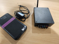 DMX Kit used and mounted inside the top of the standing lamp (USB battery bank, step up power supply and wireless RGB dimmer)
 -
 Transmitter setup in Ath control room


With several practicals and quite a substantial Act1 to Act2 set change, the power up and pre show checks were key to ensuring a good rig and running of the show:
PLX powerup/down and pre show checks