Into The Woods 2023: Difference between revisions
| Line 268: | Line 268: | ||
Image:Into the Woods -Picture Frame 5.jpg |Frame mounted on back box with diffusion | Image:Into the Woods -Picture Frame 5.jpg |Frame mounted on back box with diffusion | ||
Image:Into the Woods -Picture Frame 6.jpg |Velcro tab securing back box to frame | Image:Into the Woods -Picture Frame 6.jpg |Velcro tab securing back box to frame | ||
Image:Into the Woods -Picture Frame 11.jpg |Test | Image:Into the Woods -Picture Frame 11.jpg |Test photo in frame | ||
Image:Into the Woods -Bedroom Lamp & Picture Frame Wireless DMX Dimmer.jpg |Wiring both the lamp and picture frame to dimmer | Image:Into the Woods -Bedroom Lamp & Picture Frame Wireless DMX Dimmer.jpg |Wiring both the lamp and picture frame to dimmer | ||
</gallery> | </gallery> | ||
Revision as of 12:12, 8 December 2023
.
| Into The Woods 2023 | |
|---|---|
| Summary | |
| Dates 4th - 9th December 2023
| |
| Location New Athenaeum
| |
| Creative Team | |
| Director | |
| Designer | |
| Lighting Designer | |
| Sound Designer | |
| Video Designer | |
| Production Team | |
| Stage Supervisor | |
| Deputy Stage Supervisor | |
| Stage Manager | |
| Deputy Stage Manager | |
| Assistant Stage Manager | |
| LX Programmer | |
| PLX | |
| Technical Stage Technicians | |
| Sound 2 | |
| PSE | |
Overview
Into the Woods is a Stephen Sondheim musical that cleverly intertwines classic fairy tales like Cinderella, Little Red Riding Hood, Jack and the Beanstalk, and Rapunzel. The characters venture into the woods to fulfill their wishes, but the consequences of their actions unfold in unexpected ways. The first act follows their pursuits, while the second explores the aftermath.
Technical Stage Department
Iris Effect
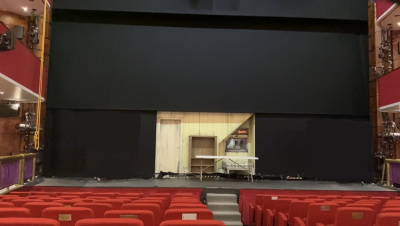
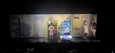
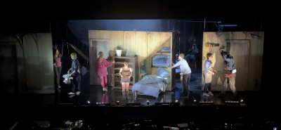
The desired effect for the opening on both Act1 and Act2 was to be 'irised' into a letterbox opening on the single bedroom truck. It then opened one side at a time revealing the other two flats either side. They then in one movement were to all disappear into the wings along with the full tab flying out and the truck revolving around.
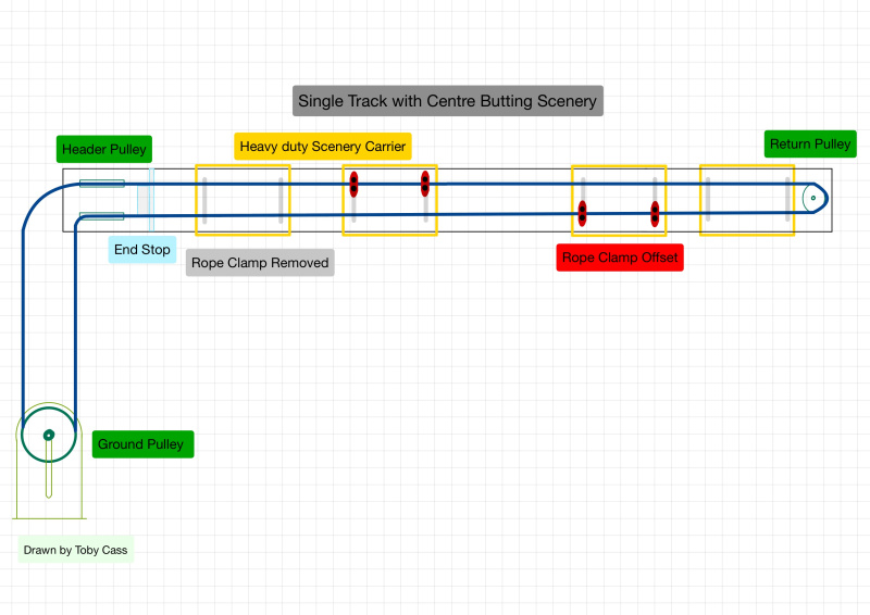
This was achieved by rigging a 17m 300 box truss from the underside of each fly floor which then had two separate tracks on the US & DS cords. These tracks were fitted with 3 separate tracking systems:
The DS track had two independent single track straight wipe systems which operated a hard masker on scenery carriers followed by a 6x6m black tab that was on curtain runners. The US track had a centre butting system, meaning the two door flats were on the same system so when you pull on the rope one way the flats move in opposite directions (mirrored). The way the flats were mounted, was using two heavy duty scenery carriers with half doughty mounted below, a Scaff pipe then joined the two carries a flats width apart. Off of that same Scaff pipe were 2 x T piece Kee Klamps. By using a torque of 39Nm they can hold an axial load of 900kg per grub screw. So two 6m Scaff pipes were then rigged off them down to half doughty bolted to the flats. The aim of this rigging method was to keep the weight of the flats as under the carriers as possible to prevent a skewed resting angle.
Moon
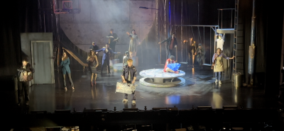
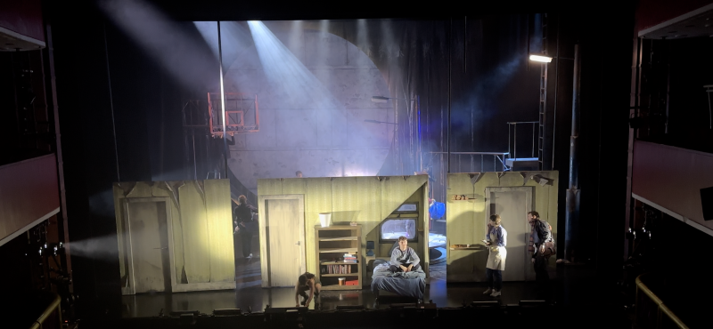
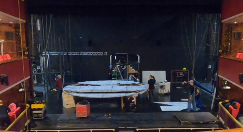
The moon is the largest set piece on this show. Its a 6m diameter frame made from an old revolve, which was layered with twin wall and painted cloth to create a 3D texture on the front face. There is also a double hinged door off centre left which required a balcony platform from behind to access.
This first photo shows the size of the moon in relation to the stage. Along with the scenic and construction departments working on it before rigging.
This second image below, shows the moon on the build truss, this was to allow LX to mount LED battons around the circumference before it was transferred to its final position which was too close to the theatre back wall to access with ladders.
The image to the right shows the moon hanging on its automation points infront of the balcony platform that comes in from the void. There is then a backcloth flown in behind on CW 29 which has a hole cut in it to access through to the moon.
Automated Movers
During the planning stages there was a requirement to move two moving lights IN/OUT to create a specific lighting effect on stage. We chose to use two BigTow winches to achieve this as it would give us the speed we needed but also the repeatably high accuracy every time. We also brought in black truss from NTS as when it flys in you can see the movers from the audience.
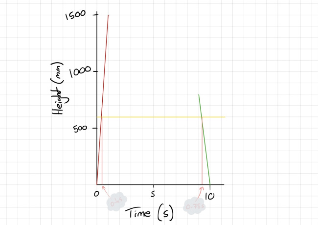
The effect desired was a physically moving beam of light, which then stays targeted on a single object centre stage. This then proved slightly harder than initially thought as when you press go on the auto cue, there is a period if time it takes to ramp up to the desired velocity and equally as is decelerates to come to a stop. The lighting programmer can plot a graph to which their cue runs to however we needed to know how long the acceleration and deceleration actually takes. We achieved this by plotting an AVD graph as seen below in Vectorworks, then using the tape measure tool to measure the length which equates to seconds.
I knew from the EpiQ desk that the accel was set to 1500mm/s^2. The velocity was 600mm/s. And the decel was set to 800mm/s^2. Total Cue time = 9.599s
So plotting a line from 0 (initial speed) to 1500mm over 1 second, then a constant at 600mm you can see where they intersect and draw a line down and measure from 0 again giving us 0.4 seconds. The same again for decel plotting 800mm over 1 second, intersection at 600mm, line down, measure to end of timed cue 9.599 seconds = 0.75s seconds. This plotted Trapezoid AVD graph is now to ramp up and down of that specific cue.
The LX programmer could then plot the exact same graph into the MA2 to achieve a smooth and linked* move.
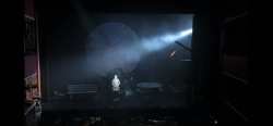
Below are two photos of the difference in beam position that this effect creates.
Auto Cameras
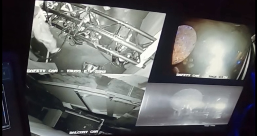
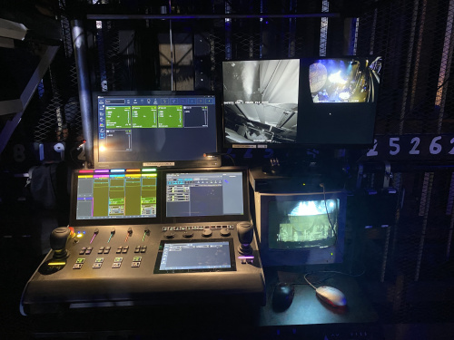
Due to the very busy wings on this show the automation desk couldn't go in a place with a clear line of slight of both automated set pieces. So it was positioned under the staircase that goes up to the USR platform. To overcome this issue we setup 3 serrate cameras around the set to monitor areas which might be affected when the set pieces are moving. The first (Top Right) is an overview of the stage, but facing predominately into the MSL wing as this is where the truss flys In to 1m. The second (Top Left) is a top down view of exactly where that truss is going to land, this is to make sure no-one or set is under it as it come to stage. The third (Bottom Left) is a camera placed above the moon balcony, this allows me to see that the doors on the moon are shut before it falls, and also to make sure that any crew of cast members are clear of it when quickly swoops away from the platform. Lastly in the bottom right I have a feed from show relay to give me a front on view of the stage. This also proved very useful to have backstage for other things other than auto!
Platforms
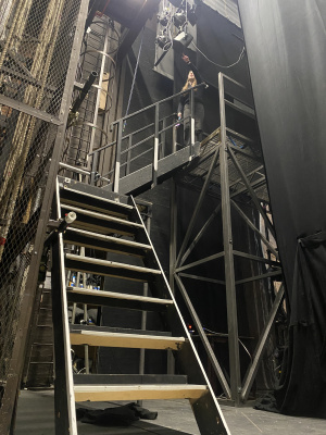
This show had a very 'climbable' set, almost everything was made or reinforced for acting on, from the large 4m platform USR to the tiny tin bins with stage weights and reinforced lids. This meant access to all these high areas had to be thought of and built into the offstage wing planning. At first when all the set was delivered to the stage most platforms were accessed via ladders, however once the large platform was in place the SM team decided some of the cast would find going up a ladder so high quite difficult under time pressure etc. Therefore we devised a large staircase method which you can see below.
The second image above is of the 'rolling get off platform' this is a truck that is never seen by the audience but rolls around the SR wing meeting the bedroom truck in whichever position it is in to provide access on and off the step which can been seen on stage. The angle of the bedroom truck also changed a lot so the rolling platform has a drawbridge that can be lowered to cover the gap created when the two don't meet flush.
Ground Plans
Sound
Design
Comms
To connect our wired and wireless comms
- 3 Pin XLR out of wired comms basestation to in house patch
- From in house patch, XLR to 4-wire, into wireless comms basestation
To get wireless control pad
- Wireless basestation network settings
- Connect to basestations wifi
- Enter IP address in browser
Our settings
Meant that all wireless comms were constantly on B ring for our 'stage ring', but are still able to hear the DSM's show call.
Everyone on wired comms on A ring and are unable to hear wireless B ring.
B ring on wired comms was available too, separate wireless B ring, but are unable to hear the DSM.
Hollyland Solidcom C1 HUB8S Control Pad
A Group - Default 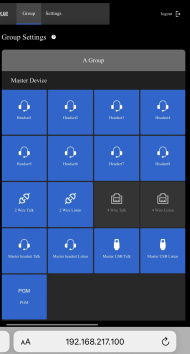 B Group - Default
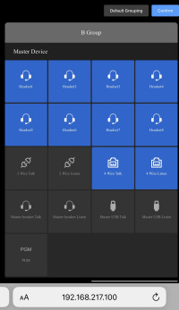
A Group - Changed 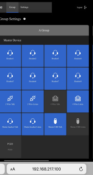 B Group - Changed
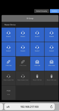
Equipment and Power
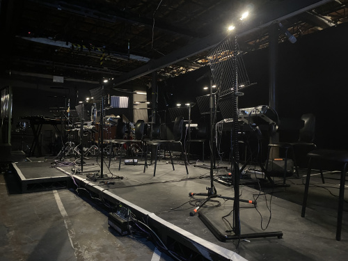
Pit: Uses of power = 13amp and 16amp. Our DQ rack which distrobutes signal to the digico desk is powered by 16amp found in the upsatge left corner of the pit. we postioned our DQ rack at the front of the pit, DSL. This was because we had four subs on this show, two B1 - L + R and two C7 Subs - L + R. these were powered by amplifiers inserted in our DQ rack in the pit. We avoided long unwated runs of NL4(speaker cable) and were able to concentrate all of our cable runs at the front of the pit where easily accesible and out of the way of band memebers.
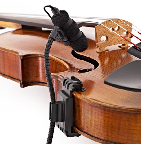
Nineteen microphones were used in our pit band. Microphone types included: DPA 4099 - Violins, Violas, Bass, Cello which were all attached using specific clips designed for each instruments. For example a violin clip:
Piccolo Snare Drum - AT2020 Snare Drum - AT2020 Bass Drum - SM89 Tom-toms - SE300 Cymbal (Suspended) - SE300 Small Choke Cymbal- SE300 Horn I - beta 57 Horn II - beta 57 Trumpet - MD441
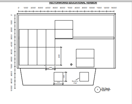
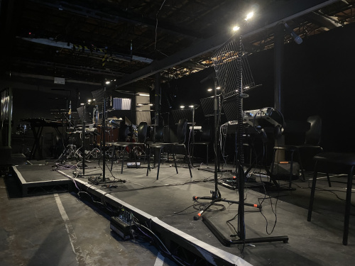
Each instruments microphone is connected to the DQ rack in the inputs section via XLR cable. Once connected the digico SD12 in use is able to pick up their signal via dnate network. We used three stage boxes around the pit in order to control the amount of cable needed. See Image below.
Our main cable run was along the front of the situated steel deck we used bungies to attach the cables to the steel rungs. This was because it is fast and easy to attach, adjust-access cable, strike and is much more environmentally friendly than tape. The cables consisted of XLR, Cat 5 ethernet and power for our stage boxes
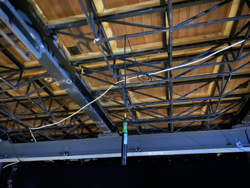
Some instruments it made sense to hang mics,The infrastructure of the pit allowed us to easily hang mics. See image below:
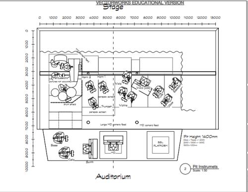
Pit PLan:
We layed black painted steel deck, this blacked out the grey floor in the pit, allowed us to manage cable runs better and added a certain elegance to the pit. We also rigged a black drape around the back of the pit to cover any unwanted storage.
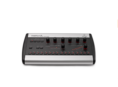
In order for each band member to essentially have their own foldback we used a behringer powerplay system, beheinger base station connected to two distrobuters which distrobuters to each musicians powerplay unit, this small P16-M mixer allowed the musicician to switch between different groups within the mix. for example, strings Vox etc. Adjust volumes, pan, add effects etc. Headphones were required.
Pit Steel Deck Layout
Onstage:
Lighting
The LX dept had some interesting obstacles to overcome in the implementation of the LX rig, as well as the design and manufacture of some practical set pieces.
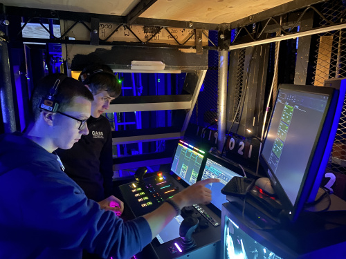
Two Martin Quantum Wash units were rigged on a short 1.5m section of truss which was required to fly live during the show to mimic a tracking sun. In order to facilitate and easy controlled movement, TSD made use of the automation system and programmed the truss to move. Whilst the setting up of the automation winches and programming the cue was relatively easy, because the truss flew live, we also needed to ensure the operator had a clear view of the area that the truss flew in and out of. To do this, a setup of a digital HD low light camera was installed onto the LX boom directly below the truss, and the feed from the camera was routed through the house patch, to the automation programmers position US.

-
Truss Above Camera
-
Camera on Boom
-
Screens at Automation Control
With all of this in place, the LX Team then realised we needed to understand the curve/track timing of the automation cue, to allow us to try and replicate the speed and movement of the truss. This meant calculation a Velocity over Time graph:


![]()
![]()
This resulted in the LX OP being able to tweak the "DMX Profile" of the lighting cue using the percentage option in MA2 software to try and match the cue. By making the start of the cue run quickly, then remaining constant, and finally slowing, the Tilt of the moving head, closely matched the profile of the Automation cue. This allowed the beam of light from the fixture to remain focussed on one piece of set, whilst the physical height of the fixture was altered.
Two set piece items which LX were asked to solve were a bedside lamp and picture frame, that could both be operated wirelessly and be under DMX control to avoid performers having to switch them on and off on cue.

The bedside lamp was a relatively easy project, and just required the changing of the sourced lamps bayonet lamp holder to an Edison screw, so that we could make use of a stock LED filament lamp that can operate at 12v. A hired wireless DMX system comprising of a transmitter, powerful omni directional aerial, 3 channel 12v wireless dmx dimmer, and USB battery power system was used to provide 2 channels of dimming - one for the lamp and one for the picture frame. To modify the bedside lamp, we first tried using and bayonet B22 to Edison screw E27 adapter but this made the bulb sit too high above the edge of the lamp shade, so it was poking out! To remedy this the lamp holder was simply removed, rewired, and the plug removed to provide bare wire to attach to the dimmer:
-
Bedside Lamp with Adapter - bulb too high
-
Bulb and Adapter
-
Rewiring the bulb holder
-
Rewiring the bulb holder
Making the picture fraem light up, took a little planning and forethought. First a box would need attached to the rear of the picture frame to give a suitable depth to mount some LED product. From experience, it was decided the LED should be mounted at 90degrees to the actual picture, and a "lightbox" created to give as soft a light source as possible to illuminate through the image. The back box was constructed from 5mm black foam board, and lined with a fresh uncrinkled piece of aluminium foil. Some 2 cell 4000k warm white led modules were mounted around the edge of the box. This box was then covered by a piece of Lee diffusion to again soften the light source.
-
Picture Frame LED modules
-
LED modules mounted in back box with foil
-
Diffusion
-
Frame mounted on back box with diffusion
-
Frame mounted on back box with diffusion
-
Velcro tab securing back box to frame
-
Test photo in frame
-
Wiring both the lamp and picture frame to dimmer
Lighting Design
LIGHTING PLANS
Version 1 of the Lighting Plan - created in June 2023 before rehearsals had started.
Version 4 of the Lighting Plan - this was the final rig plan that was used for the get-in.
Version 5 of the Lighting Plan - this is the updated plan post first preview.
Rig change notes.
Lighting Magic Sheet - this is what I used to plot the show from.
LIGHTING CUE SHEET
LIGHTING NOTES
