Setting Initial Limits on the Winch
Setting the Initial Limits on the Automation winches is crucial when operating them. Although it may not be the easiest of tasks, setting them could save a lot of problems and damage if the desk is programmed incorrectly.
The initial limits are set on each winch individually, and are a physical cut switch when the winch reaches the extremes of it's safe travel. This prevents the lines being pulled through the grid, or being coiled on the floor. There is no desk override for the initial limits.
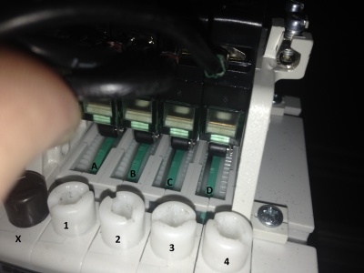
Physical Layout
The limits are controlled by a set of cam disks and micro-switches, which are set by turning the corresponding white plastic screw.
The Outer 2 screws control the absolute limits of the winch, which is the total distance the motor can physically wind or unwind. The inner 2 screws are the ones we are interested in, as these adjust the initial limits.
DO NOT TURN THE BLACK SCREW, THIS CHANGES THE GEARING OF THE CAM DISKS
Setting Limits
Screw Assignment
X - Cam Disk Gearing Adjustment DO NOT CHANGE 1 - Absolute IN Limit (Cable OFF drum) 2 - Initial IN Limit (Cable OFF drum) 3 - Initial OUT Limit (Cable ON drum) 4 - Absolute OUT Limit (Cable ON drum)
Cam Disk Assignment
A - Absolute IN Limit (Cable OFF drum) B - Initial IN Limit (Cable OFF drum) C - Initial OUT Limit (Cable ON drum) D - Absolute OUT Limit (Cable ON drum)
IN Limit (Screw 2, Cam Disk B)
-Run the line IN until it is in contact with the floor. -Turn screw 2 until cam disk B lifts the micro switch, then turn it back slightly to disengage the switch.
OUT Limit (Screw 3, Cam Disk C)
-Run the line OUT until it is just below the grid. -Turn screw 3 until cam disk C lifts the micro switch, then turn it back slightly to disengage the switch.

