Carousel 2013
| Carousel 2013 | ||||||||||||||||||||||
|---|---|---|---|---|---|---|---|---|---|---|---|---|---|---|---|---|---|---|---|---|---|---|
| ||||||||||||||||||||||
Carousel
| ||||||||||||||||||||||
Carousel marks the second year of the large scale musical theatre performance within the Conservatoire.
Company
Creative Team
Director: Andrew Panton
Musical Director: Simon Beck
Choreographer: Emily-Jane Boyle
Associate Director: Susie Dumbreck
Set Designer: Alex Lowde
Lighting Designer: Simon Wilkinson
Sound Designer: Blair Omond
Projection Designer: Tim Reid
Technical Production Team
Stage Manager: Jack Hirst
Deputy Stage Manager: Amber McClelland
Assistant Stage Management:
Technical Stage Manager: Rebecca Coull
Chief Flyperson:
Stage Technicians:
Chief Electrician: Neil Foulis
Deputy Electrician: Audrey Wilson
Sound Designer/ Sound Number 1: Blair Omond
Sound Number 2: Laura Dougan
Lighting Operator: Audrey Wilson
Electricians:
AV Operator: Robert Butler
Sopt Operators: Keiran Fitzpatrick & Shannon Howard
Sound
Sound Number 1 and Sound Designer - Blair Omond
Sound Number 2 - Laura Dougan
Sound Department Kit List
Control Kit
- 1x Midas Pro 6 Console (FOH)
- 1x Midas DL371 (Control Room)
- 2x Midas DL251’s (Control Room and Pit)
- 1x Klark Teknik DN9331 Graphic (FOH)
- 1x Apple Mac G5 with Protools and QLAB 2
- 1x Digi Design 003 Rack
Speakers and Amps
- 2x d&b E12’s (Stalls Left and Right)
- 4x d&b E8’s (1st and 2nd Circle Left and Right)
- 2x d&b Qi7’s (Bottom of Centre Cluster)
- 3x d&b Qi Subs (Upper Section of Centre Cluster in Cardioid Arrangement)
- 4x d&b E0’s, Black (Stalls Front Fills)
- 12x d&b E0’s, White (Stalls, 1st and 2nd Circle Delay Fills)
- 6x d&b E3’s (Stage Foldback)
- 11x d&b D6 Amps (10x Permanent Install, 1x Rack Mounted in Pit)
- 1x d&b D12 Amp (Permanent Install)
- 1x Mackie Powered Monitor (MD Monitor)
Radio Microphones
- 6x Shure UR1M Packs
- 17x Shure UR1 Packs
- 1x Shure UR2 (Director’s God Mic)
- 12x Shure UR4D Dual Receivers
- 23x DPA 4066 Pink Headsets with Mini XLR Connector
Radio Microphone Show Frequencies
All G1E Frequency Band, UHFR, 10mW Transmitter Power
- 510.400 MHz - Phil Atkinson - Starkeeper and Doctor Seldon
- 501.775 MHz - Greg Barrowman - Mr Bascombe
- 487.325 MHz - James Baxter - Ensemble
- 486.975 MHz - Emily Byrt - Julie Jordan
- 525.950 MHz - Ruby Day - Carrie Pipperidge
- 524.650 MHz - Ryan Ferrie - Enoch Snow
- 515.500 MHz - Will Gosnold - Policeman and Ensemble
- 514.025 MHz - Danni Irvine - Nettie Fowler
- 491.675 MHz - Lyndsey Knox - Mrs Mullin
- 490.900 MHz - Thomas Milligan - Ensemble
- 495.350 MHz - Hayley Mulcrone - Ensemble
- 494.150 MHz - Chris Pollard - Billy Bigelow
- 497.025 MHz - Charlotte Smith - Ensemble
- 495.775 MHz - Jeff Smyth - Jigger Craigin
- 524.300 MHz - Ashlee Rose Soldo - Ensemble
- 522.900 MHz - Kara Swinny - Ensemble
- 490.300 MHz - Sarah Swire - Louise Bigelow and Ensemble
- 488.300 MHz - Beth Taylor - Ensemble
- 519.425 MHz - Matthew Tomlinson - Ensemble
- 518.075 MHz - Claire Wallis - Heavenly Friend and Ensemble
- 513.525 MHz - Robert Wallis - Ensemble
- 511.100 MHz - Alistair - Enoch Junior
- 521.775 MHz - Saoirse - Enoch’s Daughter
- 520.200 MHz - Andrew Panton - Director
Microphones / DI Boxes
- 6x AKG SE 300’s
- 2x DI Boxes
Microphone Stands / Cabling
- 1x Stereo Mic Bar
- 4x Straight Stands (E0 Front Fills)
- 7x 20m XLR Cables (Pit)
- 1x 3m XLR Cable (Pit Amp Patch)
- 1x 16 Way 5m XLR Loom (Radio Mic to Stage Box in Pit)
- 1x 8 Way 5m XLR Loom (Radio Mic to Stage Box in Pit)
- 1x 16 Way 3m XLR Loom (Control Room Amp Patch)
- 1x 8 Way XLR to 1/4” Jack Loom (DigiDesign to Desk)
Orchestra
All of the orchestra were located in the orchestra pit
- 2x Flutes
- 1x Oboe
- 2x Clarinets
- 1x Bassoon
- 3x French Horns
- 2x Trumpets
- 3x Trombones
- 1x Tuba
- 1x Harp
- 2x Piccolos
- 4x 1st Violins
- 3x 2nd Violins
- 2x Violas
- 2x Cellos
- 1x Double Bass
- 1x Percussion
Stage Management
Stage Management Sources
| Item | Source | Contact | Notes |
|---|---|---|---|
| Crates of clams | Made at the Royal Conservatoire of Scotland
Clams sourced from Mussel Inn, Gamba, Rogano |
We sourced the clams from Mussel Inn, Gamba, Rogano - seafood resturants in Glasgow. We attached the clams to the top of some shoe boxes to make the crates weigh lighter. These were removable from the crates for after the Clambake | |
Confetti |
Halo Lighting | Halo Lighting
98 - 124 Brewery Road London N7 9PG Tel: 0844 844 0484 http://www.halo.co.uk/ |
The designer wanted a 6 minute confetti drop. I managed to source a bag of flame proof confetti for £15.00 p/kg |
| Fried Chicken Boxes | Chunky Chicken | Address: 532 Sauchiehall St, Glasgow, G2 3LX
Phone:0141 332 1772 |
Chunky Chicken was able to supply us with several takeaway chicken boxes for the Prolgue. These were to be non-branded. We put pieces of bread in to look like chicken |
| Doughnuts | Sainsburys | Buchanan Galleries
236-240 Buchanan St, Glasgow 0141 332 1480 |
Sainsburys were happy to donated us with approx. 20 doughnuts as we are registered charity |
| Deck Chairs | Lawn Chairs USA | http://www.lawnchairusa.com/ |
Technical Stage Management
Revolving Stage (Dundee Rep Revolve)
The revolving stage was borrowed from Dundee Rep, the surrounding stage and ramps were built by RCS workshops.
The first thing to look at with this is powering it. It requires a 16Amp 3-phase supply. The available supply in the venue is 125A 3-phase. In order to reduce this we required jumps, distro and a variable RCD, which we hirded from Tower Productions, Edinburgh.
Distro Hired from Tower Productions
( Note: This is also the order in which it should be connected from the venue supply to the revolve motor control.)
- 125Amp 3-phase to 63Amp 3-phase Jump
- 63A 3-phase in-line variable RCD
- 3metre 63A 3-phase extension
- 63A 3-phase to x2 32A 3-phase & x1 16A 3-phase distribution box
- 20m 16A 3-phase extension
Revolve Operation
Once the revolve is built and powered up it can be operated from the control box. For this show it was situated in the DSL wing by the DSM position, allowing the operator a direct line of sight to the revolve. The operator also had a monitor showing a view from overhead of the revolve to allow them to check the edge was clear and to mark stopping positions on.
Unfortunately with this revolve a cue stack cannot be created and as we also experienced issues with it slipping or losing it's count (position) the revolve had to be stopped and started manually on the control desk, rather than programming a stopping point (which was in theory possible). For this the operator marked her monitor with points to hit stop at so it would decelerate and stop at the correct point.
Programming cues on the revolve
Power up
Chief Electrician or Venue Technician to turn on mains at wall.
Ensure Revolve Clear
- Beige box on floor DSL - turn red switch to on.
Wait for consol (black box on table) to boot up and show main screen.

Check both Emergency stops released
- Pull E-stop on Consol up.
- Twist and release e-stop on side of prompt desk.
Press green button on beige box (it should click).
Set up
Once powered up the revolve will require zeroed as it forgets this information when turned off.
- To set zero press (and hold briefly) the jog (joystick logo) activate button until the logo flips down.
- Press and hold clockwise jog button (CALL REVOLVE MOVING) to turn Revolve until it finds zero. The START button (at top) will activate and the degree count will start counting.
The Revolve is now ready to programme.
Note: Each cue will require programming prior to running (no cue stack).
Operation and Cue programming
To programme start with the Settings screen

The direction, speed, number of revolutions and stop position is set here.
Direction
- Clockwise (CW)
- Counter clockwise (CCW)
Speed (in revolves per minute)
- Fastest speed – 3
- Slowest speed – 0.5
Revolutions
- Number of revolutions from zero
When counting revolutions revolve will start count from the point where it reaches zero, turn the number of requested revolutions then add on the stop position. (e.g. if the revolve was sitting at 5 degrees, was set to 3 revolutions and had a stop position of 180 degrees – it would run the following 355 degrees to zero, revolve 3 complete times and then run from 0 to 180.)
Stop position
- From 0.0 to 359.9
To revolve one complete turn from zero the revolve must be set to zero revolutions and then programmed to stop at 359.9 as it will not recognise a 0 to 0 command.

Setting Acceleration and deceleration
To set this, go into the System screen.
The fastest acceleration and deceleration speed is 10 degrees.
Note: this is very sudden and causes sudden movement, particularly noticeable at higher speed settings. The revolve is also prone to slipping when set to decelerate suddenly from speed.
Also in System page
Teach setting – this is only to be used to completely reset the revolve in case of large discrepancy in the position; it allows the revolve to relearn all it’s positions – this must only be done by TSM or Workshop.
Index/constant – switches revolve between just turning continually and operating to marked points.
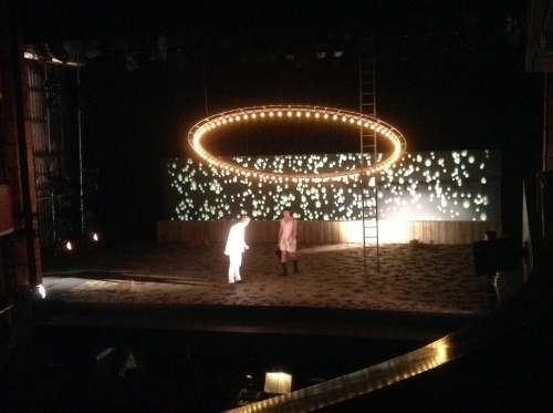
Halo Ring on Automation
Overview
One of the main features of the design was the halo ring which lit up and flew in to almost the deck and out to amongst the Lx rig, it also was required to tilt on an US-DS axis. This was tricky as it required that the Lx bars were rigged on trapeze bars and on very precise points on the bars – please see Lx Trapeze Bar pots for details.
The other challenge with this was rigging it from the automation itself, various methods were discussed; including counterweight slave bars, flying it directly from the winch lines and hanging truss or bars from the winch lines to then hang the halo from. In the end we went with the final option as the weight change when it tipped would have made weighting it correctly on a counterweight bar difficult; we could not fly it directly from the lines at the winch line drops can only be placed in particular positions on the grid and none of these lined up correctly with the pick up points on the Halo. The final option was what we went with, the automation lines ran down to a bridle, which was attached to a pair or scaffold steel bars clamped together with vertical couplers, from this 6m drifts to the ring itself. This allowed us the greatest control over the weight distribution and tilt.
Stats
- Halo ring constructed in 3 sections which are bolted together.
- Individual section weighs 53kg – complete halo weighs 159kg (plus weigh5t of scaffold bars on the winch lines) .
- The Halo has an outside diameter of 6 metres.
- The pick-up points on the halo are if put into a square 3895mm from each other.
- We set the minimum height the halo came in to as 300m, the absolute maximum it could fly out was 6500mm.
Equipment Used
- X4 Stage Technologies winches
- X4 Short black and red 24kN strops
- X4 3.2T shackles
- X8 1.5m drift
- X8 1T shackles
- X8 ¾ T shackles
- X4 6m drifts
- X8 barrel clamps
- X8 vertical scaff couplers
- X4 7.4m lengths of steel scaff.
Rigging
Pairs of steel bars are attached together using 4 vertical scaff couplers for each pair.
- The scaff couplers are spaced 985mm and 2950 from the centre of the bar out each way.
The barrel clamp points on the bottom bar (which are attached to the drifts to the halo) are 1948 from centre of the bar each way.
The barrel clamp points on the top bar (which are attached to the bridle) are 2000mm and 3400mm from the centre of the bar each way.
The each bridle is attached to the short strop from the winch line wedge socket using a 3.2T shackle to the line, two 1.5m drifts are attached to this, to a 1T shackle on the end of each drift to the barrel clamp on the bar.
The halo is attached via the remaining shackles and 6m drifts to the barrel clamp on the bottom bar.
Starkeeper's Ladder
Petal Drops
Main Petal Drop
Small Petal Drop
Lx Towers
General Notes
Masking Notes
DS Black and Gauze
Electrics
LX Photos
LX Equipment
Generic Lamps
- SL 15-32 - 21
- SL 19* - 12
- SL 23-50 - 20
- SL 26* - 8
- 1.2K Fresnel - 33
- 1.2K PC - 2
- 2K Fresnel - 11
- 5K Fresnel - 1
- PAR 64 - 30 (10 CP 61, 20 CP 62)
- S4 PAR - 1
- Birdies - 11
- Coda FLood - 28
- Orion Groundrow - 8
Special Lighting Effects
- Vari Lite 1000 tsd - 4
- Reiche and Vogul Beamlights - 2
- Le Maitre MVS Hazer - 1
- Festoon 15M - 1
Festoon
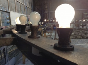
Festoon was used to create a circus atmosphere, Because this was handled by the cast, it was required to be shatterproof. it took 30 x 40 Watt pearl Shatterproof bulbs for one 15M length of festoon.
These Bulbs were bought from a supplier called Covershield.
Lightbulb Halo
The Lightbulb Halo was a main part of the set, as it was the main element representing the Carousel.
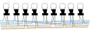
My task was to wire up all 80 Lightbulbs in 4 circuits, so it could chase and look as though they were all chasing round the ring.
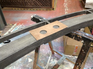
Firstly I found out the measurement between bulbs, (I used my Vectorworks plan to do this) and then made a template, see below.
I then laid out all the fittings where they go on the ring, and began wiring.
This was wired in Parallel, Each Live, and Neutral went in to the live and neutral points, and then out, and on to the next one. see explanation on Parallel wiring.
Final wiring in 4 circuits
Booms
all of the stage booms required to sit in line with the edge of the fly floor
unfortunately this meant they were sitting on the ramp up to the stage, So to solve this problem, we built small anti rakes to sit under the boom bases.
3 of the booms were to be 7 metres high, this was relatively easy to achieve, the 7M pole was tied to the fly floor, making them very rigid.
Star
the first star, (the understudy) was simple, if a little large. a simple circuit concealed inside a miniature Gin Bottle.
1x warm white LED 2x 1.5V Batteries 1x simple push switch small amount of wire.
The second star (THE star)
was another simple circuit, I used a smaller battery, and a simpler switch.
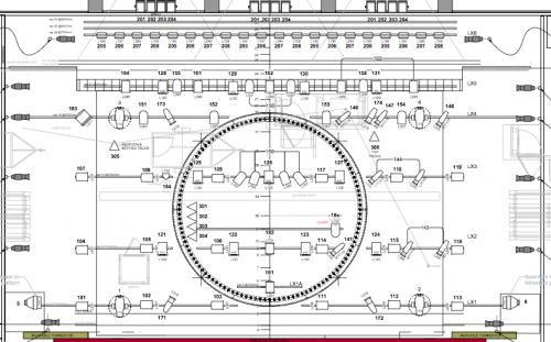
Overhead rig
(lighting plan designed by simon wilkinson)
The Halo needed to sit above the lighting bars, so it could disappear above the lamps.
this meant rigging all the bars on trapezes, the plan gives an idea of where the bars were to sit, this did mean a lot of time to work out where all the lamps were to plug in & Pair
