After Life: Difference between revisions
No edit summary |
No edit summary |
||
| (33 intermediate revisions by 6 users not shown) | |||
| Line 1: | Line 1: | ||
[[Category:Productions]] | |||
[[Category:Drama]] | |||
[[Category:New Athenaeum]] | |||
{| style=" border: 4px solid #000000; background-color: #FFFFFF; float: right; clear: right; margin: 2px; width: 22em;" | |||
! style="background-color: #000000; font-size: 150%;" align="center" colspan="2"| <span style="color: #FFFFFF;">'''{{PAGENAME}}'''</span> | |||
|- | |||
|align="center" | [[File:Afterlife cover.jpg|200px]] | |||
|- | |||
! style="background-color:#000000; font-size: 120%;" align="center" colspan="2"| <span style="font-family: Tahoma "> <span style="color: #FFFFFF;">'''Summary'''</span> | |||
|- | |||
|'''Performance Course''' <div style="text-align: centre;"> Third Year BA Acting </div> | |||
|- | |||
|'''Location''' <div style="text-align: centre;"> New Athenaeum </div> | |||
|- | |||
! style="background-color:#000000; font-size: 120%;" align="center" colspan="2"| <span style="font-family: Tahoma "> <span style="color: #FFFFFF;">'''Creative Team'''</span> | |||
|- | |||
|align="center" colspan="2"|'''Director''' <div style="text-align: centre;"> Emily Reutlinger </div> | |||
|- | |||
|align="center" colspan="2"|'''Set & Costume Designers ''' <div style="text-align: centre;"> Mia Doyle and Mairi Cameron </div> | |||
|- | |||
|align="center" colspan="2"|'''Lighting Designer''' <div style="text-align: centre;"> [[Eoin Beaton]] </div> | |||
|- | |||
|align="center" colspan="2"|'''Sound Designer''' <div style="text-align: centre;"> [[Daniel Barclay]] </div> | |||
|- | |||
! style="background-color:#000000; font-size: 120%;" align="center" colspan="2"| <span style="font-family: Tahoma "> <span style="color: #FFFFFF;">'''Production Team'''</span> | |||
|- | |||
|align="center" colspan="2"|'''Production Manager''' <div style="text-align: centre;"> Jacqui Howard </div> | |||
|- | |||
|align="center" colspan="2"|'''Stage Manager''' <div style="text-align: centre;"> Tammie Jenkins </div> | |||
|- | |||
|align="center" colspan="2"|'''Deputy Stage Manager''' <div style="text-align: centre;"> [[Jamie McDonnell]] </div> | |||
|- | |||
|align="center" colspan="2"|'''Assistant Stage Manager''' <div style="text-align: centre;"> [[Jazzi Hart]] </div> | |||
|- | |||
|align="center" colspan="2"|'''Assistant Stage Manager''' <div style="text-align: centre;"> [[George Whitley]] </div> | |||
|- | |||
|align="center" colspan="2"|'''Production Electrician''' <div style="text-align: centre;"> Jon Ross </div> | |||
|- | |||
|align="center" colspan="2"|'''Lighting Programmer''' <div style="text-align: centre;"> [[Smiles Ricci]] </div> | |||
|- | |||
|align="center" colspan="2"|'''Production Sound Engineer''' <div style="text-align: centre;"> [[Haydon Brewis]] </div> | |||
|- | |||
|align="center" colspan="2"|'''Head Of Stage''' <div style="text-align: centre;"> [[Jamie Partridge]] </div> | |||
|- | |||
|align="center" colspan="2"|'''Head of Flys''' <div style="text-align: centre;"> [[Ellie Shaw]] </div> | |||
|- | |||
|} | |||
'''Jack Thorne'''‘s play explores the mysteries of the afterlife. Join the newly departed as they face judgement and determine which memory they’ll carry with them into eternity. | |||
==Technical Stage Department== | ==Technical Stage Department== | ||
This show had several interesting components including: Performer Flying, Petal Drops and a trap. | |||
=== <u>Performer Flying</u> === | |||
During the concept meeting, the designers requested performer flying to signify one of the characters being whisked away to her final resting place. This allowed us plenty of time to design and test a system that met the requirements. | |||
==== Initial Concepts ==== | |||
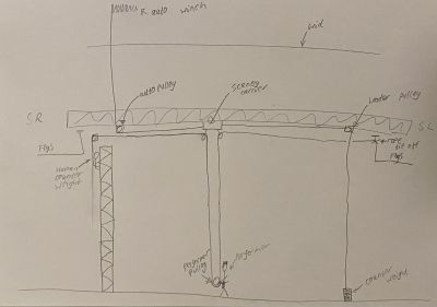
The original vision for the scene was for the performer to be flown out vertically and then we would track her off to a wing behind masking and lower her. | |||
We thought a half automated and half human counterweight system could work for this, whereby, the human counterweight controls the vertical movement and the automation controls the on to off-stage movement. | |||
[[File:Concept performer flying system.jpg|400px]] | |||
==== Final Version ==== | |||
The vision for the scene shifted over time, and the final version was the performer being flown out and off-stage right at a 45 degree angle. We realised that this would mean we could introduce a much simpler system. | |||
Our final system comprised of horizontal track, mounted to truss which spanned from SL flys to SR flys and floor-fixed black lines which were shortened by pulling a trolley along the track which the lines ran through. This perfectly created the effect that the design team were looking for. As the trolleys are pulled along the track by an automation controlled steel cable, the vertical section of black line flowed through pulleys on the trolleys, and became part of the horizontal section of line. this meant that for every metre the performer tracked off-stage, they would also gain a metre in height. Please see the final diagram below: | |||
<pdf width="975" height="750">Afterlife P-Flying Diagram.pdf</pdf> | |||
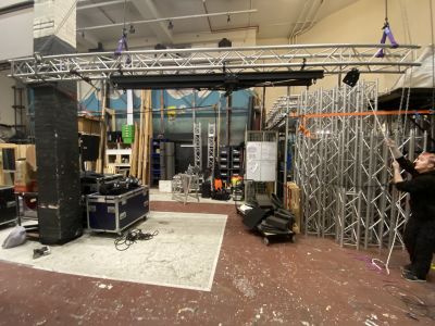
After designing this version, we built a test model in the scene dock to test that this would do as required in a practical sense. This gave us the confidence that it would work during the show. | |||
[[File:AL P-Flying dock test.jpg|400px]] | |||
==== Load Calculations ==== | |||
When undertaking rigging work, load calculations should always be done to ensure that you are not overloading any of the equipment. This is especially important when flying people. | |||
==== Pre-Rig ==== | |||
Before the actual fit-up commenced, we pre rigged the entire system (with a temporary automation pulley) so that we could test the system in the venue, as it would be for the show. | |||
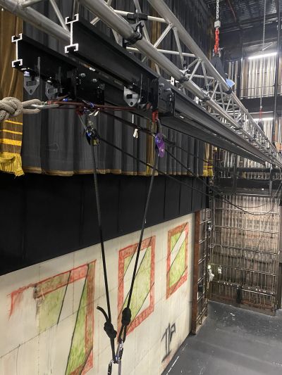
We rigged 4 Kinesys hoists body-up in the grid and attached 15 metres of Sixty-82 truss to it using choked half-metre round slings around the top two chords. HOF flew the truss out to a working height where we then attached a length of Unibeam track to each of the bottom two truss chords. We then put on the heavy duty scenery carriers, end stops, performers black lines, sandbag return line and the sandbag return line pulley. On the heavy duty scenery carrier we attached Petzl Rescue Pulleys with a carabiner and M12 eye bolts with a SWL of 2000kg. We then threaded the performer black lines through the pulleys and attached a sandbag to keep tensionWe then flew the whole truss out to a little above flyrail height where we attached the remaining 1 metre truss sections and then landed it on the rails. We fixed it down to the rails using heavy duty ratchet straps. Tension was then taken in each Kinesys hoist. | |||
[[File:Afterlife pre rig photo 1.jpg|400px]] [[File:Afterlife carriers and pulleys.jpg|400px]] | |||
===Fly's and Automation=== | |||
<pdf width="975" height="759">Afterlife Fly Plot PDF.pdf</pdf> | |||
==Electrics Department== | ==Electrics Department== | ||
<pdf width="975" height="750">After Life LX Plan.pdf</pdf> | |||
==Sound Department== | ==Sound Department== | ||
| Line 11: | Line 94: | ||
The requirements for the content system needed playback for Qlab and a head mic; we used the in-house Digico SD12 and a Mac studio for Qlab along with a two-channel rack of Shure UHFR running two packs of Shure UR1M with DPA 4061 short capped. The in-house ath sound system, mainly consisting of the D&B E series, was used along with two D&B Q7s and E3s for foldback, an effect speaker for the door and television, and four E0s for front fill. They were all powered by D&B D3 amps that ran into DQ Racks. | The requirements for the content system needed playback for Qlab and a head mic; we used the in-house Digico SD12 and a Mac studio for Qlab along with a two-channel rack of Shure UHFR running two packs of Shure UR1M with DPA 4061 short capped. The in-house ath sound system, mainly consisting of the D&B E series, was used along with two D&B Q7s and E3s for foldback, an effect speaker for the door and television, and four E0s for front fill. They were all powered by D&B D3 amps that ran into DQ Racks. | ||
===Kit List=== | ===Kit List=== | ||
| Line 45: | Line 127: | ||
File:IMG 8495.jpg | File:IMG 8495.jpg | ||
</gallery> | </gallery> | ||
===Show challenges=== | |||
We encountered a problem with the Q7 subwoofers that we borrowed regarding the NL4, as the in-house patch runs NL2, and we had to switch the wiring poles to make them work like NL2, so we made adaptors to make it only two poles rather than the four. <gallery widths="300" heights="300"> | |||
File:Q7 Sub Afterlife.jpg | |||
File:IMG 8497 (1).jpg | |||
</gallery> | |||
==Stage Management== | ==Stage Management== | ||
Latest revision as of 16:42, 23 November 2024
Jack Thorne‘s play explores the mysteries of the afterlife. Join the newly departed as they face judgement and determine which memory they’ll carry with them into eternity.
Technical Stage Department
This show had several interesting components including: Performer Flying, Petal Drops and a trap.
Performer Flying
During the concept meeting, the designers requested performer flying to signify one of the characters being whisked away to her final resting place. This allowed us plenty of time to design and test a system that met the requirements.
Initial Concepts
The original vision for the scene was for the performer to be flown out vertically and then we would track her off to a wing behind masking and lower her.
We thought a half automated and half human counterweight system could work for this, whereby, the human counterweight controls the vertical movement and the automation controls the on to off-stage movement.
Final Version
The vision for the scene shifted over time, and the final version was the performer being flown out and off-stage right at a 45 degree angle. We realised that this would mean we could introduce a much simpler system.
Our final system comprised of horizontal track, mounted to truss which spanned from SL flys to SR flys and floor-fixed black lines which were shortened by pulling a trolley along the track which the lines ran through. This perfectly created the effect that the design team were looking for. As the trolleys are pulled along the track by an automation controlled steel cable, the vertical section of black line flowed through pulleys on the trolleys, and became part of the horizontal section of line. this meant that for every metre the performer tracked off-stage, they would also gain a metre in height. Please see the final diagram below:
After designing this version, we built a test model in the scene dock to test that this would do as required in a practical sense. This gave us the confidence that it would work during the show.
Load Calculations
When undertaking rigging work, load calculations should always be done to ensure that you are not overloading any of the equipment. This is especially important when flying people.
Pre-Rig
Before the actual fit-up commenced, we pre rigged the entire system (with a temporary automation pulley) so that we could test the system in the venue, as it would be for the show.
We rigged 4 Kinesys hoists body-up in the grid and attached 15 metres of Sixty-82 truss to it using choked half-metre round slings around the top two chords. HOF flew the truss out to a working height where we then attached a length of Unibeam track to each of the bottom two truss chords. We then put on the heavy duty scenery carriers, end stops, performers black lines, sandbag return line and the sandbag return line pulley. On the heavy duty scenery carrier we attached Petzl Rescue Pulleys with a carabiner and M12 eye bolts with a SWL of 2000kg. We then threaded the performer black lines through the pulleys and attached a sandbag to keep tensionWe then flew the whole truss out to a little above flyrail height where we attached the remaining 1 metre truss sections and then landed it on the rails. We fixed it down to the rails using heavy duty ratchet straps. Tension was then taken in each Kinesys hoist.

Fly's and Automation
Electrics Department
Sound Department
Requirement
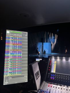
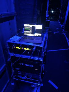
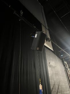
The requirements for the content system needed playback for Qlab and a head mic; we used the in-house Digico SD12 and a Mac studio for Qlab along with a two-channel rack of Shure UHFR running two packs of Shure UR1M with DPA 4061 short capped. The in-house ath sound system, mainly consisting of the D&B E series, was used along with two D&B Q7s and E3s for foldback, an effect speaker for the door and television, and four E0s for front fill. They were all powered by D&B D3 amps that ran into DQ Racks.
Kit List
Speaker Patch
Sound Department Photos
Coms
We used the in-house Techpro for wired and wireless, an 8 set of Holyland C1 running two wire to connect the wireless.
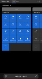
There was a custom setting setup for a total of 3 separate rings, two hard-wired and one wireless. The A hard-wired and A wireless were used for show calling, and the Hardwired B was used for Lighting, sound and the director. The wireless B was used for TSD and stage management.
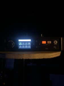
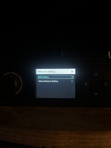
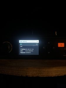
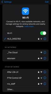
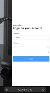
This was configured through the Hollyland wireless software, which is accessed by holding down on the select button, selecting network setting, turning on the wireless network, then connecting the wireless network via a phone or laptop by selecting the network HLD_345D7B3
Then, into your web browser, enter 192.168.217.100; then you will reach a log-in page with an admin password 12345678; you will then access the settings to change the com’s channel allocations.
Show challenges
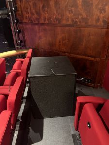
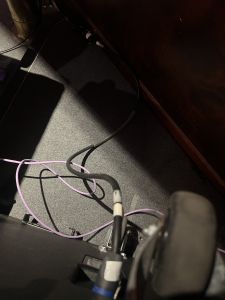
We encountered a problem with the Q7 subwoofers that we borrowed regarding the NL4, as the in-house patch runs NL2, and we had to switch the wiring poles to make them work like NL2, so we made adaptors to make it only two poles rather than the four.

