Countdown Timer: Difference between revisions
Susanscott (talk | contribs) |
SMacluskie (talk | contribs) No edit summary |
||
| (2 intermediate revisions by 2 users not shown) | |||
| Line 1: | Line 1: | ||
[[Category:Projects]] | |||
[[Category:Classroom Projects]] | |||
This is a project created by [[Francesca Branch]], [[Jane Gordon]], [[Alix Ross]] and [[Susan Scott]] for PLX classes 2008. | This is a project created by [[Francesca Branch]], [[Jane Gordon]], [[Alix Ross]] and [[Susan Scott]] for PLX classes 2008. | ||
| Line 36: | Line 40: | ||
== Images == | == Images == | ||
[[Image:Image-front.jpeg]] | [[Image:Image-front.jpeg]] | ||
[[Image:Back.JPG]] | [[Image:Back.JPG]] | ||
[[Image:Paper.JPG]] | [[Image:Paper.JPG]] | ||
Latest revision as of 12:09, 5 December 2012
This is a project created by Francesca Branch, Jane Gordon, Alix Ross and Susan Scott for PLX classes 2008.
Idea
The original idea was to create a countdown timer similar to those that you see on a bomb on television.
Process
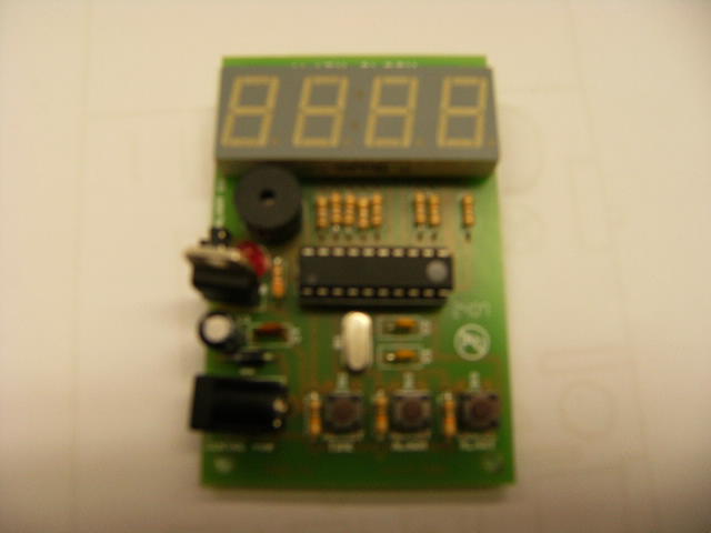
After much thought we decided it would be easiest to get a kit from Maplin. There were two that we could have chosen, one being a countdown timer the other being an alarm clock that we would try and reverse...After much deliberation it was decided that we should attempt to modify the alarm clock as this would teach us more about how to use different components.
The kit was assembled by soldering and once everything was in place we tested it to make sure it worked. We then tried to think of a way to reverse the timer, this involved ideas such as gates and a different type of chip. However having gone back to Maplin to see if they had a chip to change the direction we found they were rather unhelpful and therefore did not want to buy a chip which could quite possibly not work.
Having decided that we could not make it work as a countdown timer we chose to leave it as an alarm clock.
Components
The main components in this circuit are:
A 7-segment display consists of seven light emitters,LEDs arranged in a figure of 8. Different numbers can be produced by lighting appropriate segments of a 7-segment display.This is use to display the time until the bomb goes off.
intergrated circuits (the chip in the centre of the ciruit)are the brains of circuits,it controls which leds are on in the 7-segment display.
LED aka light-emitting diode, is a semiconductor diode that emits light. LEDs are often used as small indicator lights on electronic devices and increasingly in higher power applications such as flashlights in this case to indicate when the bomb is about to explode and also in the 7-segment display to display the time.
A resistor is a two-terminal electrical or electronic component that opposes an electric current by producing a voltage drop, thus lowering the voltage so it doesn’t fry the circuit
the capacitor, is an device that can store energy in the electric field between a pair of plates. This process of storing energy is known as "charging", and involves electric charges of equal magnitude, but opposite polarity, building up on each plate.Capacitors are used in this electrical circuit to provid a constant supply of electricity.
Ceramic capacitor is a device that is used now to provid a lower cost alternitive to capacitor types. It is use here to simply lower the cost of manufacting.
An electrical signal can be amplified by using a device that allows a small current or voltage to control the flow of a much larger current. Transistors are the basic devices providing control of this kind.
Transistors are devices that can control an electrical signal can be amplified by using a device that allows a small current or voltage to control the flow of a much larger current. In the case of this circuit providing the current for the buzzer and led.


