PLX 08 Mirror Ball: Difference between revisions
No edit summary |
SMacluskie (talk | contribs) No edit summary |
||
| (2 intermediate revisions by 2 users not shown) | |||
| Line 1: | Line 1: | ||
[[Category:Projects]] | |||
[[Category:Classroom Projects]] | |||
== Group Members == | == Group Members == | ||
| Line 18: | Line 22: | ||
== Diagram | == Schematic Circuit Diagram == | ||
[[Image:Schematic.jpg|thumb|left|Schematic Drawing]] | |||
[[Image:Schematic.jpg|thumb|Schematic Drawing]] | |||
Latest revision as of 12:10, 5 December 2012
Group Members
Marthe Hoffman, Ricky Smith, Ashley Thomas and Calum Wyllie.
Outline
We intend to construct a electronic chasing sequence circuit, consisting of LEDs within a mirrorball.
Construction
With the help of Ricky managing to get a mirrorball we could chop up, we split the mirrorball into four sections using a pyrograph. The mirror ball was easily cut as it was hollow. In between each of the four sections we cut seven little grooves so seven LEDs could sit flush in the polystyrene. They were held in place with LX insulating tape, allowing us to solder bell wire onto the ends of the LEDs. This process was repeated for each of the other sections. We thought it would be a nice idea to incorporate a sequencer within the mirrorball so that the LEDs would flash on and off.
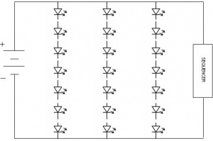
It is made of three series circuits, with seven parallel circuits within each series. Please refer to the diagram below for more information.
Schematic Circuit Diagram
